
SoapBox Snap Arduino Ladder Logic Tutorial
Before you can use SoapBox Snap to program an Arduino in ladder logic, you need:
- A PC with Windows XP, Windows 7, or later
- An Arduino UNO, Nano or Mega (R3)
- The Arduino Software
- (Read the Getting Started tutorial if you’ve never used an Arduino before)
- Install the Timer1 Library for Arduino
- The Phidgets Driver Library – choose the appropriate 32 or 64 Bit Installer Download and install it, and make sure you have Phidgets 21, not 22.
- Install SoapBox Snap (version 2014.07.06 or later)
- Note that if you want to use an Arduino Mega or want to configure any digital pins as analog (PWM) outputs, then you need version 2015.01.11 or later.
- When you install SoapBox Snap, it will install .NET 4 if you don’t already have it
- If you’re on Windows 8, make sure you have both the .NET framework 3.5 and 4.0 (or 4.5)
Note: I’m assuming you’re familiar with ladder logic, or you wouldn’t be here. I don’t assume you know C++.
After you’ve completed the steps above, connect your Arduino via the USB cable, and then open the SoapBox Snap Arduino Firmware, which is automatically installed in this folder:
C:\Program Files (x86)\SoapBox Automation\SoapBox Snap\ArduinoFirmware\
Double-click on the “ArduinoFirmware.ino” file, which is an Arduino “sketch”. If you have the Arduino software installed (linked above) then this will open the sketch in the Arduino IDE. Follow these steps to download the firmware to the Arduino:
- In the menu Tools->Board, make sure you have the correct Arduino board selected (to match your physical hardware). This should be “Arduino Uno”, “Arduino Nano w/ ATmega328” or “Arduino Mega 2560”
- In the menu Tools->Serial Port, make sure you have your Arduino’s serial port selected (remember this port number for later too)
- Optionally, if you have the Nano or Mega, you can edit the BoardSelect.h file and comment out the “#define UNO” line and uncomment either the “#define NANO” or “#define MEGA” line. (Two slash marks is a comment: //) This will allow you to use all 8 analog inputs on the Nano, rather than only the first 6 that are available on the Uno, or use all the available analog and digital I/O on the Mega. If you decide to do this, you’ll have to mark the BoardSelect.h file as read/write (instead of read-only). You have to do this in your Windows file system, not in the Arduino software.
- Make sure you’ve imported the Timer1 library. Go to the menu Sketch->Import Library->Add Library… and browse for the zipped library file you downloaded in the pre-requisites section above. (This should be in a folder called TimerOne, not TimerOne-r11, or the Arduino IDE might complain.)
- Now use the menu to go to File->Upload. This will first compile it and then upload it to the board.
- If it worked, the LED connected to pin 13 on the board should be blinking one short blink every 1 second. Optionally, you can connect to the board from within the Arduino software by using the menu item Tools->Serial Monitor. Set the baud rate to 115200. Now you can type some commands. Try typing “status” without the quotes and press enter. It should say “Running=False”, then “EOM”. You can also try “information”. you can even try reading the status of an input now: “read b0” will read the status of input pin 3, “read b1” will read the status of input pin 4, and so on. “read n0” will read the value from analog input A0, etc.
- Bonus: try the “device-config” command. This will read back a list of the I/O configuration. Arduino discrete I/O pins are configurable as either inputs, outputs, or analog (PWM) outputs. By default all discrete pins are configured as inputs, but you can change a pin to an output. For example, if you want pin 8 to be an output, send the command: “config-output 8”. If you want pin 9 to be an analog (PWM) output, send the command: “config-pwm 9” At any time, you can change them all back to inputs with the command “config-reset”. Note that this in only for informational purposes at this time. You have to do this through SoapBox Snap later, as you’ll see, or all your configuration changes will be wiped out the first time you download your ladder logic to the device.
- When complete, you can close the Arduino software.
Now you can start SoapBox Snap. The installer will have installed a shortcut on your desktop, or you can find it in the start menu (it’s under the SoapBox Automation folder). When you start SoapBox Snap, it opens the SoapBox Snap Start Page. On the left of the start page you will see some links. Click on the “New Program” link. Now on the left you will see a Solution Explorer window. Inside that window, the top level object is the Solution, and under this is the Runtime. We need to start by changing the properties of the Runtime:
- Right click on the Runtime item and select Properties… from the context menu
- In the properties page that opens, there is a Type drop-down box. Select “SoapBox Snap Arduino Runtime” from the drop-down list
- In the Address text box, enter the COM port of the Arduino from above (e.g. mine is “COM27” without the quotes)
- Optionally, in the Configuration text box, you have to enter the I/O configuration information. Unfortunately you have to be very precise here. What you need to do is specify which discrete I/O pins will be outputs (by default they’re all inputs). For example, if you want pins 7 and 8 to be outputs, you would enter on the first line: “config-output 7” (without quotes) and “config-output 8” on the next line.
- As of version 2015.01.11, you can also configure certain pins as analog (PWM) outputs. Only some pins are configurable as PWM outputs. They should be marked on your board, but you can look them up on the Arduino site as well. The Uno and Nano PWM pins are 3, 5, 6, 9, 10, and 11. The Mega PWM pins are 2 to 12 and 44 to 46 (pin 13 is technically a PWM pin but we’re using that as a status LED). To configure one of the PWM pins as an analog (PWM) output (e.g. pin 9), the syntax is “config-pwm 9”.
- Click the Apply button in the bottom right corner of the runtime properties window
- Click the Save icon on the toolbar (looks like a floppy disk). It will ask you where you want to save the file. That’s up to you.

A note on terminology: the Arduino world talks about “uploading” sketches to an Arduino, but in the ladder logic world we normally talk about “downloading” ladder logic programs to our PLCs. That means everything above here was talking about uploading and everything from here down is talking about downloading, but it’s really the same direction: from the PC to the Arduino.
Now you have to do your first download. This will download an empty ladder logic program, plus the Configuration you’ve entered, into the Arduino:
- Make sure you’ve disconnected the Arduino software’s Serial Port Monitor here, or else the COM port will still be in use, and SoapBox Snap can’t use it.
- Right click “Runtime” in the Solution Explorer on the left, and click Connect from the context menu
- You will be presented with an Upload/Download dialog. Always select “Download” when you get this message. This firmware does not support uploading (unless you’ve already downloaded and then disconnected from the runtime but you still have SoapBox Snap open and you try to reconnect, in which case uploading just gets back the latest download). It’s technically possible to implement uploading, but you would lose the name of all your coils, etc., and there are no plans to implement this feature (yet).
- After your download, the runtime will automatically start the ladder logic program (which does nothing because it’s empty). The LED on pin 13 will now be on steady, but flash off briefly once per second. You should see two icons beside the Runtime item in the Solution explorer: a round green arrow indicating the ladder logic is running, and a chain link with a green arrow indicating SoapBox Snap is connected to the runtime. Note that while you’re connected, the COM port is in use and you can’t connect to the Arduino with any other software.
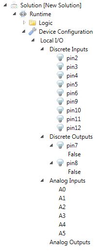
- Under the Runtime item in the Solution Explorer, there is a “Device Configuration” item. Right click on Device Configuration and select Read Device Configuration from the context menu. It will warn you that you can’t make this edit while connected. Answer “yes” when it asks if you want to disconnect. Now under Device Configuration you will see a new item named Local I/O.
- Expand the Local I/O item and all of the child items by clicking the plus (+) or arrow icons next to each item.
Here is what the solution explorer should look like, if you used the configuration shown above, with pins 7 and 8 configured as outputs:
Now you can go back online with the runtime and do some interesting things like monitor and force the discrete I/O values:
- Click the disk icon again to save
- Right click on the Runtime item and click Connect from the context menu
- Choose the “Download” option from the Upload/Download dialog
Now watch the “light bulb” icons next to the input pins. If your input pins are floating, the on/off indicators might be turning on and off already. You can also try using a jumper to connect an input pin to the 5V or GND pins to make it go on or off respectively. On my board, input pin 12 tends to flicker due to the LED on pin 13.
You can also force the outputs on or off from here. Right click on the “pin7” item (if you configured it as an output) and choose Force On from the context menu. The light bulb icon next to pin7 will light up, and you will see a forced icon (which looks like a small lightning bolt). You can measure the voltage on this pin with a voltmeter, or connect an LED to this pin through a resistor. When you’re done, please use the Release Force item from the context menu before continuing with the tutorial.
You will notice that if you expand the output pin items, there is an item underneath that reads “False” by default. This is where you connect this output to your logic. By default, the output is driven by a hard-coded “False” signal, so unless you force it on, the output will be off. You can change this to a constant “True” (always on, unless forced off), or you can connect it directly to an input pin, or a signal (like a coil) in your logic. To change the connection, double click on where it says “False” and this will open a Signal Chooser dialog. The top option is a hard coded value (enter either True or False here), or you can use the bottom option and select either a coil from your logic, or one of the input signals to drive it from.
A note about “Signals”: in traditional PLCs we frequently talk about bits, tags, addresses or memory locations. While this is true at a very low level in the runtime, SoapBox Snap implicitly creates these things when necessary and you don’t need to be concerned about them. When you drop a coil on a ladder rung, it implicitly allocates one bit of memory and automatically assigns the “signal” the name that you give to the coil. That means you can think of the coil, the signal, and the memory location that stores the state of that variable as all one-and-the-same. It’s just “a coil”. When you drop a contact on a rung, you use the Signal Chooser (or just type the signal name using the auto-complete textbox) to select a coil or other boolean signal to reference in that contact. Likewise, when you use a rising-edge instruction, you don’t need to allocate a special memory location to hold the state, since this is done for you. Counters and timers work the same, except that they implicitly define more than one signal each, such as “Done” boolean signals and “Current Value” numeric signals. One benefit of implicitly allocating memory is that it prevents the “beginner mistake” of using the same memory location in two different coil instructions. Most importantly it means you can focus on writing ladder logic instead of managing memory and tags.
Note: if you want to read the values of the signals over the serial port (such as into an HMI program) you’ll need some way to map the signal names into the internal addresses in the Arduino. As of version 2015.11.01, you can now export a signal table to do exactly this. At the top of the screen, go to Tool -> Options… and go to the Soapbox Snap Arduino Runtime options page. Check the box there for Export Signal Table, and in the text box, enter the fully qualified directory where you want it to export. The next time you download your logic to the Arduino, it will write the signal table to a .csv file in that directory.
Writing ladder logic for the Arduino Runtime is the same as for the Soft Runtime that’s included in SoapBox Snap. Open the main ladder logic page by expanding the solution explorer tree under Runtime->Logic and then double-clicking on the Main item. A single empty rung will have been created by default. The available instructions show up in a visual list on the right. You can drag and drop these instructions onto the rung. New rungs can be added by right clicking in the ladder editor and using the context menu. All of the instructions except “Find Text” will work with the Arduino Runtime (it has no use for String instructions right now). Note that each rung is called a “group” or “instruction group” (for reasons that are unimportant).
SoapBox Snap supports online debugging but not online editing, so you have to disconnect to make your edits and then connect again to download your changes. Some things to note:
- The ladder logic program is stored in the Arduino’s EEPROM memory, so it will survive a reboot or loss of power
- There is no “retained” or “persistent” memory, so all of your coils, timers, counters, etc. will revert to default values, both on a download or turning off the power
- Connecting to the Arduino with SoapBox Snap doesn’t cause a reset, but connecting with the Arduino Software’s Serial Port Monitor will
- The current version of the runtime limits the size of the ladder logic program to 750 bytes (3750 on the Mega), including overhead stuff. This probably equates to about 50 “average” rungs (250 on the Mega), but this obviously depends greatly on the complexity of your rungs.
- If you want to see how big the downloaded program is, connect to the runtime with the Arduino software’s Serial Port Montor, set baud to 115200, line ending to NL & CR and type “information” without the quotes, and press enter. Among the information reported will be the max size and the current program size.
- Pin 13 is hard coded to be the status LED so that I/O pin is not available. Likewise, pins 0 and 1 are hard coded to be used by the hardware serial port, so your available pins are only 2 through 12 (plus the analog inputs). On the Mega you have 16 analog inputs and additional pins 14 through 53.
If you have questions, don’t hesitate to use ask.soapboxsnap.com or email me at the address in the contact page.
– Scott
Further reading: check out these Ladder Logic Design Patterns.